Under constructions.
This preliminary page is for reference only.
 |
| The power supply has been modified by previous technician. Possibly a faulty 8V and three 7808 are used to fix it. |
 |
| Before dismantling rear panel |
 |
| Cables in the rear panel |
 |
| Rear panel removed |
 |
| Screws for rear panel |
 |
| The rear panel |
 |
| Side panel before being removed |
 |
| Cables on to the front panel |
 |
| The final transistor has been desoldered by previous technician. |
 |
| RF PA Unit |
 |
| Condition during checking |
 |
| Some burnt in the PCB |
 | |
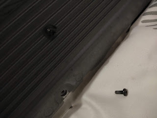
| Side screw |
 |
| Location of Silver screw |
 | |
| Screw on the side |
 |
| Remove the screw as shown to takeout the tuner unit |
 |
| This to remove PA |
 |
| How ribbon cables are placed |
 |
| From different angle |
 |
| Remove speaker cable |
 |
| After PA has been removed from the TXCVR |
 |
| PA uncover |
 |
| Replacement of PA transistors |
 |
| It has seal and vacuum |
 |
| Original bias setting, will be adjusted later |
 |
| The other side of bias |
To adjust the idling current, I choose not to connect the module to the radio. But instead, perform a stand alone test. This easier, since you do not have to place the module back and reconnect cables needed.
The trick is to put into transmit mode, that is, the bias is turned on and the transistor idling current can be adjusted.
Q1 is bias switch. It is turned on when transmitting. We are going to make it on without having the PA module connected to the Radio by grounding the base of transistor. Look in the board layout and choose where you can put a small wire jumper (soldered) for this purpose.
After adjusting the idling current, I put back all and tested the radio.
It works great .. 200W !


Comments